In a traditional RTL development flow, the design is pre-evaluated at the behavioral level by system simulation. In a DSP or algorithm type of designs, the design can be evaluated with double-precision floating point math using either in C, or Matlab, or some other tools. After performance validation, the design is then re-evaluated with finite-precision math and, in many cases, approximation of some of the functions in order to fit better with hardware implementation. When the “hardware version” of the algorithm is validated, then the hardware engineers can use that as a model to verify the RTL. It is still a behavioral model of the hardware but is a “bit-exact” model. The model can be re-built inside the testbench, or called from the testbench via DPI / PLI, or used to generate test vectors. The test vector method is much easier but also less desirable as it usually does not give a good coverage (unless the vector set is really large) and is not flexible to adapt to design changes, which can happen all the time during the course of the development.
Another way to verify the design is to look at its system-level performance directly from the RTL simulation e.g.output error variance, SNR (Signal-to-noise ratio), bit error rate, etc. This is not a normal flow and usually not recommended. However, in some cases. this can be very useful and present a good/better alternative to the bit-exact model verification, for example:
- Mixed-signal verification. Analog signals by nature do not have bit-exact digital models. Slight adjustment to the design or to the input stimulus or timing may cause the output to change due to the inherent system noise. Checking that output errors are within an error margin is a better way to test this, rather than comparing in a bit-exact manner.
- When low-level hardware techniques are needed to optimize the logic. The system engineers may not know all the tricks in order to optimize the hardware implementation. So, it may be better to scope out some part of the design and let the hardware engineers experiment with it. The hardware engineers will need to look at the system performance of the design. After the design performs satisfactorily in RTL simulation, it can then be re-imported into the c model or behavioral model for the system engineers to re-validate. When I was designing a custom 16-bit floating point multiply and accumulate at Freescale, this was actually the method I used. In order to meet the timing and area constraints, a perfect design in terms of output precision could not be used and we needed to compromise the system performance to get a more optimized design.
- When it’s hard to build a bit-exact behavioral model. The reason can be as simple as (an attempt) to shorten the development time. Sometimes it can be hard to modify the floating point model to match exactly with RTL. And sometimes it could take a long time to fully validate the behavioral model’s performance. So, the system engineers may prefer to tune the algorithm parameters using a hardware accelerated platform like an emulator or an FPGA engineering model. In this case, the model given to the RTL engineers would be double-precision floating point model and the RTL engineers are responsible for converting it to finite precision math and performing preliminary verification. The final verification / validation would be done on the engineering model.
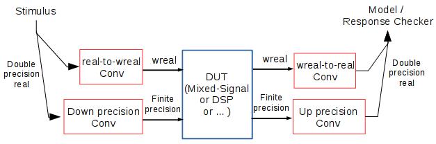
The building blocks for system-level testbenches are shown in the figure below. The extra components are
- Down-precision converter and up-precision converter for data format conversion between finite-precision and double-precision. The “finite precision” can be a fixed-point format, or floating point format, or any format used by the hardware implementation. The double precision is Verilog’s real, which is a double precision floating point format, same as C’s double and Matlab’s variables.
- Wreal to real conversion for mixed signal designs. “wreal” is for analog signal simulation in Verilog-AMS. “real” is Verilog’s real. wreal has become an industrial standard for simulating Analog circuits inside a verilog simulator. It’s less accurate than Spice or Verilog-A but runs much faster.
An example of this type of testbenches is at https://github.com/udog14/verilog_float, where the DUT is a multiply-accumulation using 2’s complement fixed point format. Other than the data conversion, we also need a few more things (which are included in the example code) to build our real-value testbench:
- Real value randomizer to generate random stimuli. SystemVerilog can conveniently generate real random values directly. We can work around in Verilog by generating random integers and converting them to floating point.
- Error margin mechanism for real value checkers. The margin can be an absolute value or a ratio of expected value or mixed. I found that a mixed margin seems to work best where an absolute error margin is used when the value is tiny, otherwise a percentage of the expected value is used.
- Real value functions like exponential and logarithm. These functions are useful to calculate system performance values like signal power, signal-to-nosie ratio (SNR), and bit error rate (BER).
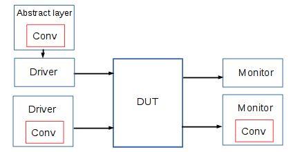
The simple testbench example uses data conversion directly inside the test. In a more structured or more complex testbench, the data conversion can be embedded inside drivers or monitors or layers above them. I once built a register abstraction layer (RAL) with built-in data conversion. This allows the upper layer, namely the tests and reference models, to work in real mode. The nice thing is that the testbench and DUT can support multiple types of finite precision without affecting the upper layer tests and models.